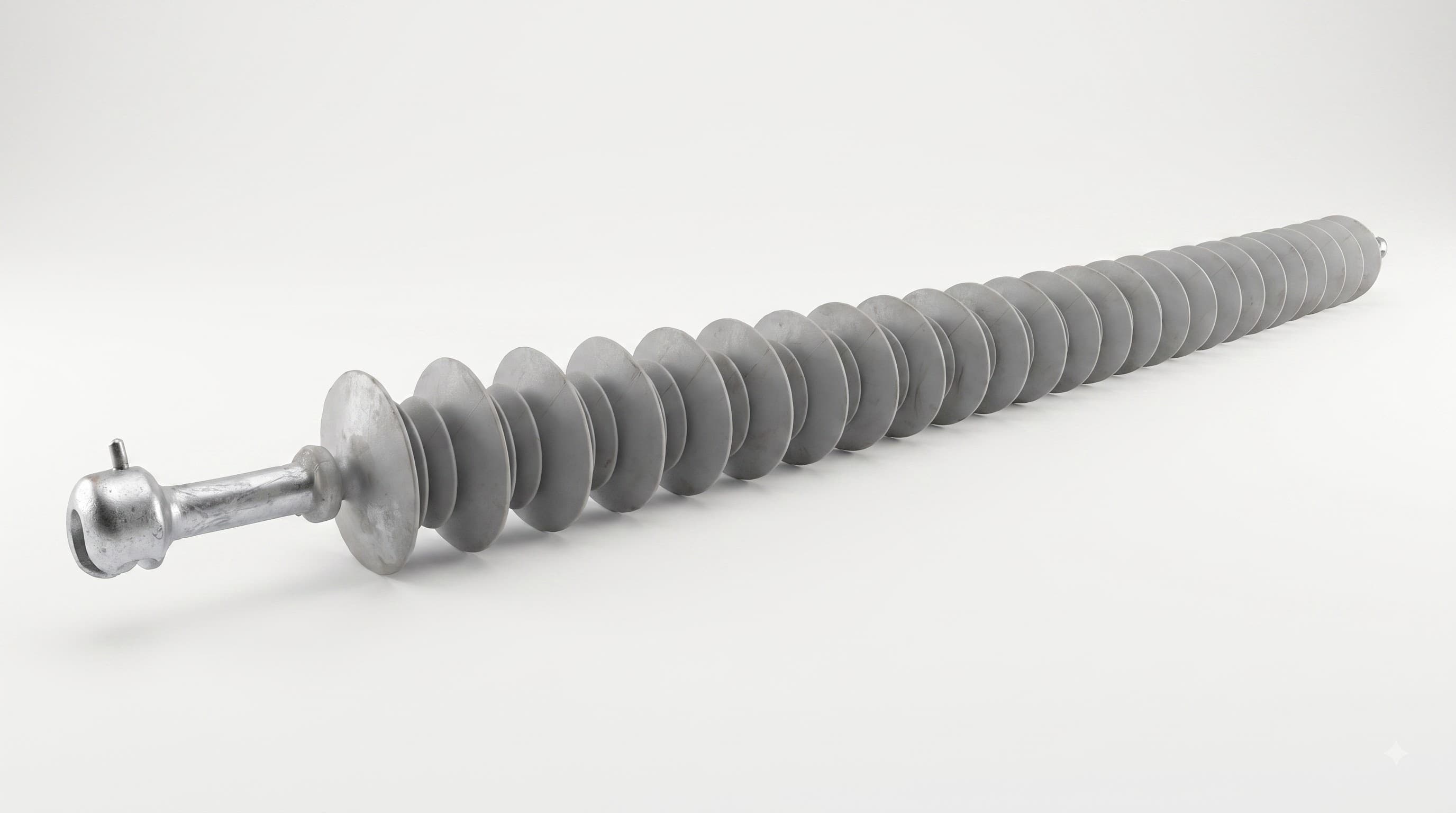
Electrical insulators perform two jobs that are easy to describe but demanding to achieve in practice: they must electrically isolate an energized conductor from an earthed structure while safely carrying the mechanical forces imposed by the conductor and line hardware.
For overhead transmission and distribution systems, one widely used solution is the Polymer Disc Insulator, also commonly described as a Composite Polymer Disc Insulator, Polymer Suspension Insulator, Polymer Tension Insulator, Composite Suspension Insulator, Composite Tension Insulator, Silicone Rubber Suspension Insulator or Composite Long Rod Insulator.
Although these names are often used interchangeably in commercial enquiries, the exact terminology can depend on the region, utility, manufacturer and construction of the insulator.
Internationally, IEC 61109 refers to this product family more precisely as composite suspension and tension insulators for overhead lines. A typical design consists of a load-bearing fibre-reinforced resin core, a polymeric housing and permanently attached metallic end fittings.
This guide explains their construction, suspension and tension arrangements, voltage classes, mechanical strength, creepage distance, end fittings, applications and the information engineers and buyers should verify before selecting a product. You can compare actual models, specifications, prices and availability in the Polymer Disc Insulator range.
For an overview of disc, post and pin designs, read the broader Polymer Insulators: Disc, Post & Pin Guide.
What Is a Polymer Disc Insulator?
A polymer disc insulator is an insulating component used primarily on overhead power lines to support or restrain a conductor while electrically separating it from the supporting tower, pole, cross-arm or other grounded structure.
The term “disc” can sometimes create confusion.
Traditional porcelain and toughened-glass suspension strings are frequently assembled from a number of individual cap-and-pin disc units. A modern composite suspension/tension insulator, by contrast, commonly uses one continuous load-bearing FRP rod surrounded by polymer sheds, rather than a string of separate ceramic discs.
For this reason, engineers may also call it a:
- composite suspension insulator;
- composite tension insulator;
- polymer long rod insulator;
- silicone rubber suspension insulator;
- silicone rubber tension insulator;
- composite string insulator;
- polymer strain insulator.
IEC 61109:2025 covers composite suspension and tension insulators consisting of a cylindrical solid insulating core, generally glass fibres in a resin matrix, a polymeric housing and permanently attached metal end fittings.
Why Is It Called a Suspension or Tension Insulator?
The terminology usually describes the mechanical duty and position of the insulator on the line.
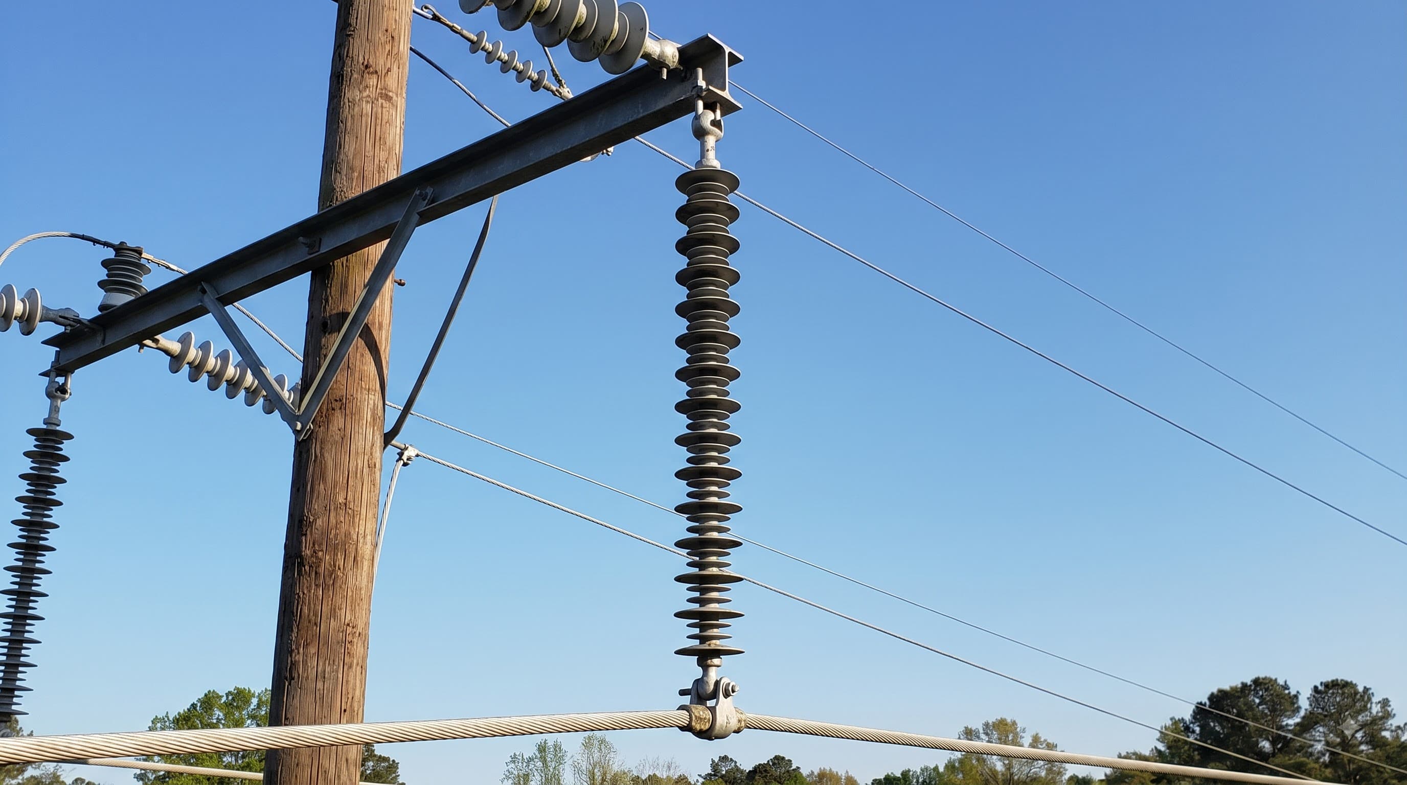
A suspension arrangement generally supports the conductor at an intermediate structure.
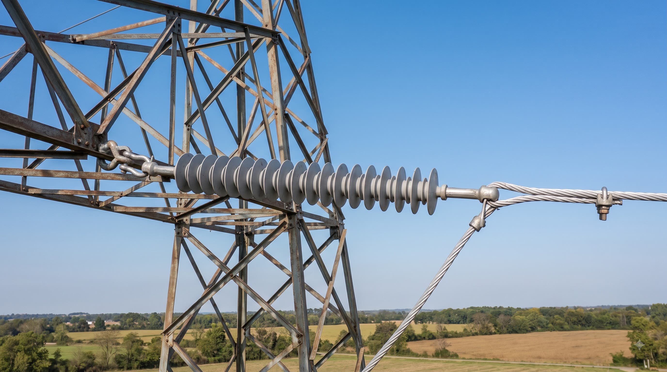
A tension arrangement resists longitudinal conductor tension and is commonly found at dead ends, major line-angle locations and termination points.
The physical product can therefore look similar while being selected and installed for different mechanical duties.
Construction of a Polymer Disc Insulator
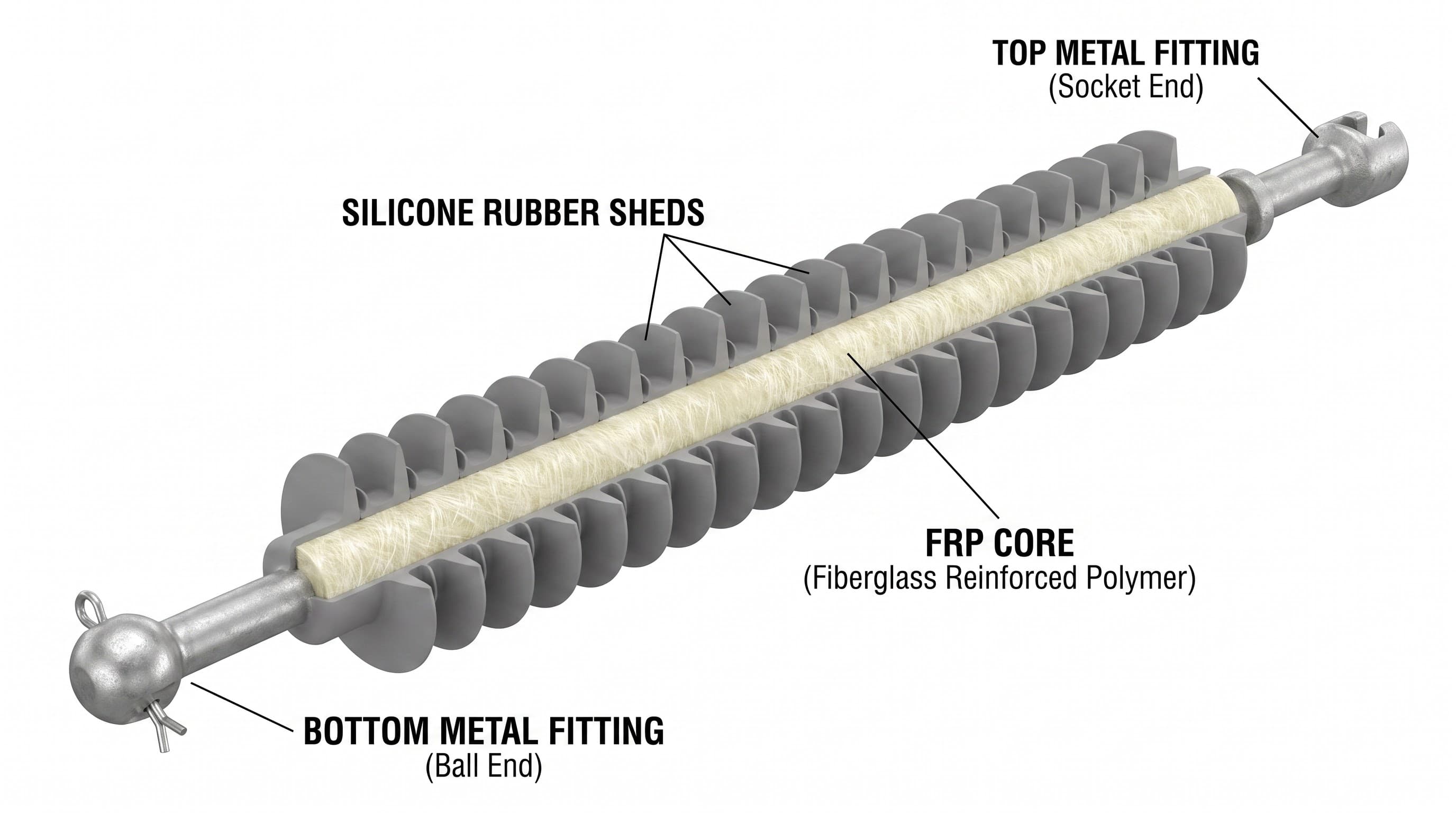
A typical composite suspension/tension insulator has four important functional areas:
- FRP load-bearing core;
- silicone rubber or other polymeric housing;
- polymer sheds;
- metallic end fittings and their connection to the core.
Understanding these components makes it easier to understand both the mechanical and electrical behaviour of the insulator.
FRP Core Rod
The central component is normally a fibre-reinforced polymer rod, commonly called an FRP or fibreglass core.
This rod performs the main load-bearing function.
In a suspension or tension arrangement, the core must withstand substantial tensile forces transmitted between the conductor hardware and supporting structure.
IEC describes the core of a composite suspension/tension insulator as a load-bearing cylindrical solid core made of fibres, usually glass, in a resin-based matrix.
The required core construction and dimensions depend on factors such as:
- specified mechanical load;
- insulator length;
- fitting design;
- electrical design;
- applicable standard;
- customer or utility specification.
A higher voltage rating does not automatically mean the same mechanical rating. Electrical and mechanical requirements must be considered separately.
Silicone Rubber Housing and Sheds
The FRP core is enclosed by an insulating polymer housing.
For many modern composite insulators, silicone rubber is used as the external housing and shed material.
The housing protects the core from the external environment, while the sheds extend the surface path between the energized and grounded ends.
One important property of silicone rubber is hydrophobicity, meaning its surface tends to repel water rather than allowing water to spread easily into a continuous film.
Research on silicone-rubber outdoor insulation shows that hydrophobic behaviour can help inhibit formation of continuous wet conductive paths on contaminated surfaces. It is also important to recognize that hydrophobicity can change with ageing, contamination and electrical/environmental stress, so it should not be treated as an unlimited or permanent property.
Metallic End Fittings
Metal fittings are permanently attached at both ends of the FRP core.
They transfer mechanical load between:
tower or pole hardware → insulator → conductor hardware
Depending on the specification, composite string insulators can use couplings such as:
- Ball & Socket;
- Tongue & Clevis;
- Tongue;
- Clevis;
- Eye;
- Y-clevis;
- combinations of these connection systems.
IEC 61466-1 specifically covers standard strength characteristics and several standard end-fitting arrangements for composite string insulator units.
Appropriate corrosion protection, commonly including galvanizing for suitable steel or iron components, is also important for outdoor service.
Core-Housing-Fitting Interfaces
The interfaces between the FRP core, polymer housing and metallic fittings are critical areas of composite-insulator design.
Manufacturing needs to create:
- a strong mechanical attachment;
- appropriate sealing against environmental ingress;
- a stable interface between different materials;
- repeatable dimensions;
- reliable quality control.
The latest IEC 62217 revision includes test requirements and evaluation considerations related to polymeric materials, core materials, housing/core combinations, interfaces and end-fitting connections.
Manufacturers may use controlled crimping or compression processes for the end fittings and suitable moulding processes for the housing. The exact manufacturing method should be judged against the approved product design and applicable test requirements rather than by marketing terminology alone.
How Does a Polymer Disc Insulator Work?
A polymer suspension/tension insulator simultaneously manages electrical stress and mechanical load.
Mechanically, the FRP core carries the conductor-related load between the fittings at both ends.
Electrically, the insulating core and polymer housing prevent current from following an intended conductive path from the energized conductor to the grounded support.
The sheds increase the surface path along the insulating housing.
This surface path is particularly important when an outdoor insulator is exposed to:
- rain;
- dust;
- industrial pollution;
- coastal contamination;
- humidity;
- airborne deposits.
The required insulator design therefore cannot be selected from voltage alone.
Polymer Suspension Insulator vs Polymer Tension Insulator
One of the most important distinctions is between a suspension arrangement and a tension or strain arrangement.
| Parameter | Polymer Suspension Insulator | Polymer Tension / Strain Insulator |
|---|---|---|
| Main function | Supports suspended conductor | Resists longitudinal conductor tension |
| Typical line position | Straight/intermediate sections | Dead ends, angles, terminations |
| Mechanical loading | Primarily conductor weight plus environmental loads | Significant longitudinal tensile force |
| Common name | Suspension insulator | Tension or strain insulator |
| Selection basis | Voltage + mechanical load + geometry + environment | Voltage + required tensile duty + geometry + environment |
| End fitting | According to project arrangement | According to project arrangement |
Polymer Suspension Insulator
A Polymer Suspension Insulator is commonly installed where the conductor hangs below or from a supporting structure.
Typical locations include:
- tangent or straight-line towers;
- intermediate support points;
- suspension structures.
The conductor weight and environmental forces such as wind contribute to the mechanical duty.
Polymer Tension or Strain Insulator
A Polymer Tension Insulator, also frequently called a Polymer Strain Insulator, is used where the conductor produces substantial longitudinal tension.
Typical positions include:
- dead-end towers;
- terminal structures;
- significant line-angle structures;
- conductor termination points;
- tension sections.
A tension assembly should therefore not be selected simply because another insulator has the same nominal voltage.
Its required mechanical rating and hardware arrangement must also match the line design.
Important Technical Ratings of a Polymer Disc Insulator
A complete specification contains much more information than “11kV polymer insulator” or “33kV disc insulator.”
Several parameters should be checked.
1. Voltage Rating
Polymer suspension and tension insulators are manufactured for different system voltages.
The current Rashtriya Electrical disc-insulator catalogue includes product names across 11kV, 15kV, 22kV, 33kV, 66kV, 132kV, 220kV and 440kV applications. Available combinations differ by individual product.
A buyer should also distinguish between terms such as:
- nominal system voltage;
- rated voltage;
- highest system voltage;
- power-frequency withstand voltage;
- lightning impulse withstand voltage.
These values are related but they are not interchangeable.
2. Mechanical Strength in kN
Mechanical strength is one of the most important specifications for suspension and tension insulators.
Product ranges may include classes such as:
| Mechanical Rating | Typical Meaning |
|---|---|
| 45kN | Specified mechanical class for relatively lower mechanical duty |
| 70kN | Common suspension/tension mechanical class |
| 90kN | Higher mechanical load requirement |
| 120kN | Heavy mechanical duty |
| 160kN | Higher-strength transmission application |
The Rashtriya Electrical catalogue currently records products using 45kN, 70kN, 90kN, 120kN and 160kN classes.
The mechanical rating relates to the insulator's specified mechanical duty according to its design and applicable test requirements.
The correct mechanical class must be established from the line design, taking into consideration factors such as:
- conductor tension;
- conductor size;
- span;
- wind;
- line angle;
- dead-end duty;
- ice loading where relevant;
- safety factors;
- hardware configuration;
- utility specification.
3. Creepage Distance
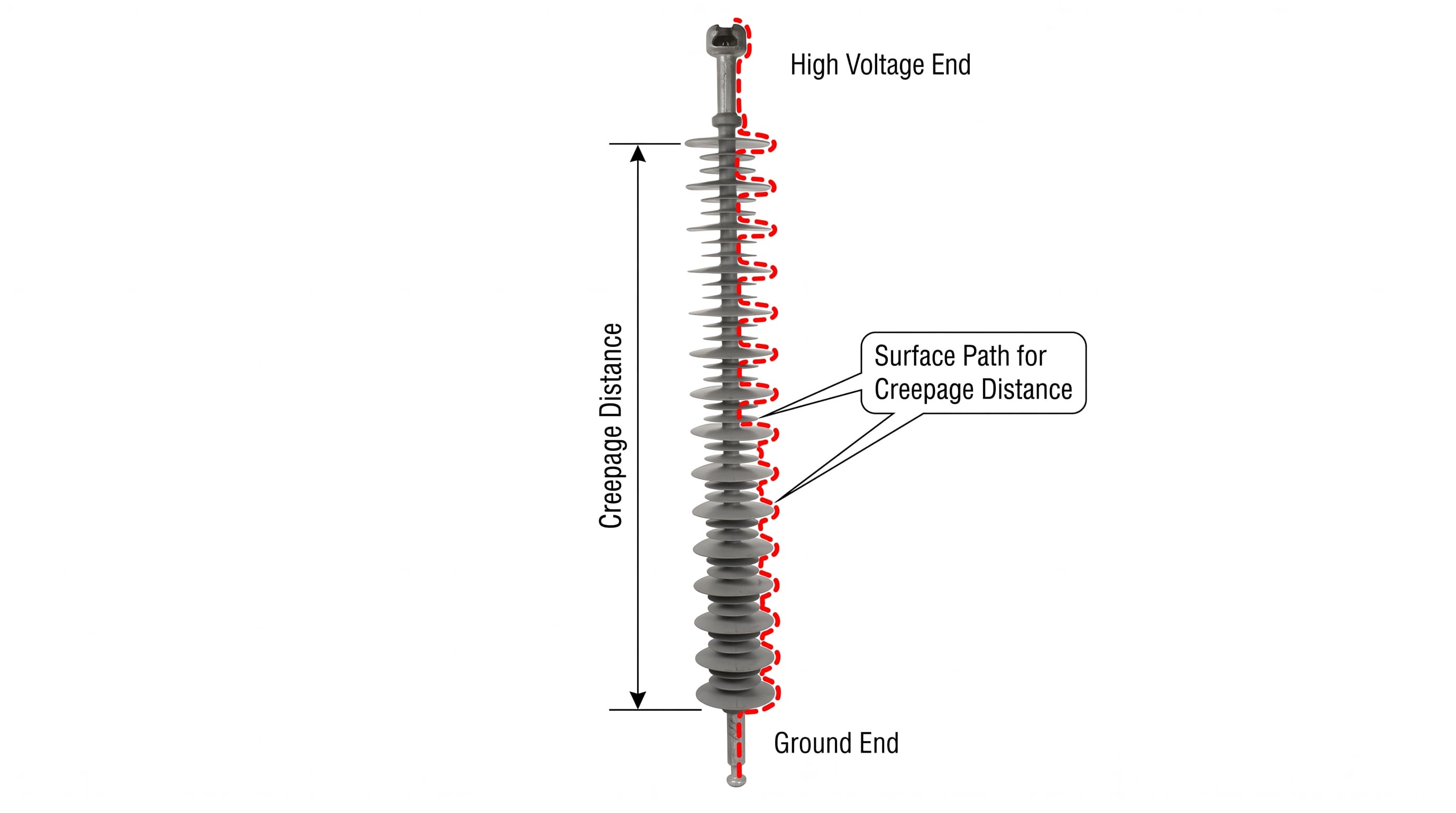
Creepage distance is the distance measured along the insulating surface between conductive parts.
For outdoor high-voltage insulation, the required creepage design is closely linked to pollution conditions and insulator geometry.
The IEC 60815 series provides guidance for selecting and dimensioning high-voltage insulators for polluted conditions. The current polymer-specific document, IEC TS 60815-3:2025, considers factors including site pollution severity, insulator profile, altitude, geometry and the characteristics of hydrophobicity-transfer materials.
This means there is no technically responsible rule that says:
“Every 33kV polymer insulator must always have exactly X mm creepage.”
The required value depends on the project.
For example, some current Rashtriya Electrical 33kV Polymer Disc Insulator listings specify 1116mm creepage distance with 11 sheds. This should be treated as the recorded specification for those products, not as a universal 33kV requirement.
4. Dry Arcing Distance and Electrical Withstand
Creepage distance should not be confused with dry arcing distance.
Broadly:
Creepage distance follows the surface.
Arcing distance represents a shortest air path between electrodes/end fittings under the relevant geometry.
Electrical specifications may also include:
- dry power-frequency withstand;
- wet power-frequency withstand;
- lightning impulse withstand;
- switching impulse withstand where applicable.
The required values should come from the approved project specification and applicable standard.
5. Shed Profile and Number of Sheds
The shape, diameter, spacing and number of sheds influence the external insulation design.
A larger number of sheds does not by itself prove that one insulator is “better” than another.
Engineers should assess the complete design, including:
- creepage distance;
- shed profile;
- insulator diameter;
- spacing;
- pollution environment;
- orientation;
- material;
- voltage stress;
- applicable test requirements.
Polymer Disc Insulator End Fittings and Connection Types
End fittings must mechanically connect the composite insulator to compatible line hardware.
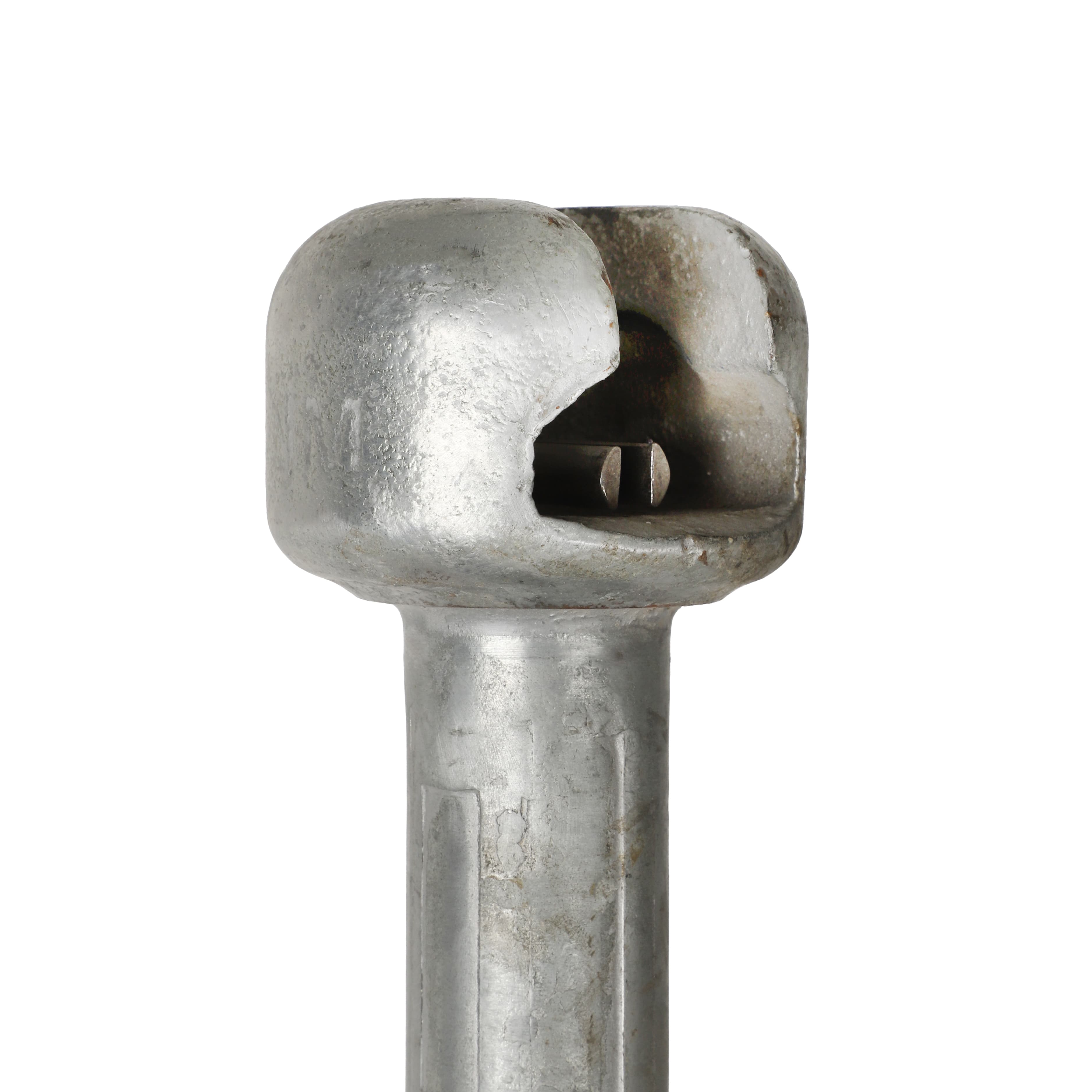
Common terminology includes the following.
Ball & Socket — B&S
A Ball & Socket arrangement uses complementary ball and socket hardware.
IEC 60120 defines dimensions for standardized ball-and-socket couplings used with string insulator units and associated fittings.
B&S configurations are widely used where compatible line hardware is specified.
Tongue & Clevis — T&C
In a Tongue & Clevis connection, a tongue fits within the clevis arrangement.
IEC 60471 defines dimensions for standard clevis-and-tongue couplings used with applicable string insulators and fittings.
Tongue & Tongue — T&T
Certain project or product configurations use tongue-type fittings at both ends.
Selection should be based on compatibility with the intended line hardware and drawing.
Tongue & Hook — T&H
A Tongue & Hook arrangement can also be supplied where the installation configuration requires it.
Because end fitting names alone do not define every dimensional detail, buyers should verify:
- coupling size;
- hole diameter;
- fitting orientation;
- fitting material;
- galvanizing;
- locking arrangement;
- drawing dimensions;
- compatibility with associated hardware.
Typical Voltage and Mechanical Configurations
A product family can contain many combinations.
The table below is a selection concept, not a universal design table.
| Voltage Class | Possible Mechanical Classes | Main Selection Considerations |
|---|---|---|
| 11kV | 45 / 70 / 90kN examples | Distribution duty, hardware, required mechanical load |
| 22kV | Depends on product | Voltage, creepage, mechanical duty, end fitting |
| 33kV | 45 / 70 / 90 / 120kN examples | Pollution level, suspension/tension role, fitting |
| 66kV | 70 / 90kN examples | Transmission/sub-transmission duty |
| 132kV | 70 / 90kN examples | Insulation level, geometry, mechanical duty |
| 220kV | 70 / 90 / higher classes depending design | Transmission application and complete insulation coordination |
| 440kV | Product/project specific | High-voltage insulation design, mechanical duty and field control |
For commercial comparison, the current Polymer Disc Insulator range allows users to review voltage, mechanical strength, connection configuration and recorded creepage information by individual model.
Polymer Disc Insulator vs Porcelain or Glass Disc Insulator
The phrase “disc insulator” is used for both traditional ceramic/glass products and composite products, but their construction can be very different.
| Feature | Composite Polymer Suspension/Tension Insulator | Porcelain/Glass Disc String |
|---|---|---|
| Main insulating body | Polymer housing over FRP core | Porcelain or toughened glass |
| Structure | Often continuous long-rod composite body | Multiple individual cap-and-pin units |
| Main load path | FRP core | Ceramic/glass unit assembly and fittings |
| Weight | Generally lower | Generally heavier for equivalent string arrangements |
| Surface behaviour | Silicone designs can provide hydrophobic behaviour | Ceramic/glass surfaces are generally hydrophilic unless treated/coated |
| Handling | Lower weight can simplify transport and installation | More individual units and higher mass may increase handling |
| Damaged element strategy | Depends on composite design and condition | Individual disc units may sometimes be identified/replaced depending on system practice |
| Ageing considerations | Polymer housing/interfaces require appropriate evaluation | Brittle inorganic materials have different failure/ageing mechanisms |
Research literature commonly identifies lower weight, favourable strength-to-weight ratio and silicone-rubber hydrophobic behaviour as important advantages of composite insulators.
However, polymer insulators are not “maintenance-free forever.” Long-term electrical, mechanical and environmental stresses can affect the housing, interfaces and hydrophobic properties, making correct design, manufacturing quality, inspection and service-condition assessment important.
Advantages of Composite Polymer Disc Insulators
When correctly designed and selected for the service environment, composite suspension/tension insulators can offer several practical advantages.
Lightweight Construction
Composite construction generally provides a lower mass than equivalent traditional ceramic-string arrangements.
Lower weight can assist:
- transportation;
- storage;
- tower handling;
- installation;
- logistics.
High Mechanical Strength-to-Weight Ratio
The FRP core provides high mechanical strength while maintaining relatively low mass.
This makes composite construction particularly useful for suspension and tension applications where tensile duty is significant.
Hydrophobic Silicone Rubber Surface
Silicone rubber can resist formation of a continuous water film because of its hydrophobic characteristics.
Research has also documented hydrophobicity-transfer behaviour in silicone-rubber systems, although the degree of hydrophobicity can change with ageing and service conditions.
Pollution Performance
Appropriately designed silicone-rubber composite insulation can perform well in contaminated outdoor conditions.
The correct creepage and profile must nevertheless be chosen according to pollution severity and service conditions rather than assuming the material alone solves every pollution issue.
IEC TS 60815-3 specifically addresses selection and dimensioning of polymer insulators with respect to pollution.
Flexible End-Fitting Arrangements
Composite insulators can be manufactured with several end-connection configurations to suit different overhead-line hardware arrangements.
Reduced Brittle Breakage Risk During Handling
Unlike porcelain and glass, the external silicone housing is not a brittle ceramic body.
This can reduce certain handling and transport damage risks, although the FRP core, fittings and seals must still be protected from damage.
Factors That Can Affect Long-Term Performance
A good engineering article should also explain the limitations.
Composite insulators operate under a combination of stresses.
These may include:
- electrical field stress;
- corona activity;
- UV exposure;
- moisture;
- pollution;
- temperature cycling;
- mechanical loading;
- chemical contamination;
- erosion or tracking;
- ageing of housing material;
- degradation of interfaces;
- damage to seals or fittings.
Research into high-voltage composite-insulator ageing identifies UV exposure, electrical discharge, pollution and environmental stresses among the factors that can degrade polymer surfaces and reduce hydrophobic performance over long periods.
Applications of Polymer Suspension and Tension Insulators
Composite suspension/tension insulators are used in many parts of the power network.
Transmission Lines
They can provide conductor support and insulation across high-voltage overhead transmission systems.
Distribution Networks
Suitable configurations can be used in overhead distribution and sub-transmission systems.
Suspension Towers
Suspension-type composite insulators support conductors at intermediate structures where the mechanical arrangement permits.
Dead-End Structures
Tension insulators can be used at dead-end or termination points where significant conductor tension must be transferred to the structure.
Angle Towers
Where the conductor changes direction, the line hardware and insulator may need to withstand substantial longitudinal and transverse forces.
Substations
Composite string-insulator designs of suitable type may also be used in certain substation arrangements. IEC 61466-1 also notes application of similar composite string-insulator designs in substations and electric traction systems.
Railway and Traction Systems
Composite insulator technologies are also used in traction applications where their design and standards are appropriate.
How to Select a Polymer Disc Insulator
Selecting an insulator should be a specification-led process.
A useful sequence is:
Step 1 — Confirm the System Voltage
Identify:
- nominal voltage;
- highest system voltage;
- AC or DC application;
- required insulation level.
Do not use nominal voltage as the only selection parameter.
Step 2 — Determine Suspension or Tension Duty
Identify the position:
- straight-line suspension;
- dead end;
- angle;
- tension section;
- termination.
This directly affects the mechanical requirement.
Step 3 — Determine the Required Mechanical Rating
Specify the required kN class according to the line-design calculations and approved specification.
Do not select a mechanical class merely because it appears commonly in a catalogue.
Step 4 — Confirm the End Fittings
Specify whether the assembly needs, for example:
- Ball & Socket;
- Tongue & Clevis;
- another approved coupling.
Also provide dimensions or a drawing when compatibility is critical.
Step 5 — Determine Creepage Requirements
Evaluate the installation environment, including site pollution severity and project standards.
IEC 60815 guidance makes clear that pollution severity, insulator profile and other correction factors can influence appropriate external-insulation dimensioning.
Step 6 — Verify Electrical Withstand Requirements
Confirm required:
- power-frequency withstand;
- impulse withstand;
- other project-specific test values.
Step 7 — Check Physical Dimensions
Depending on the project, verify:
- overall length;
- arcing distance;
- shed diameter;
- shed count;
- fitting dimensions;
- core dimensions;
- hardware orientation.
Step 8 — Confirm the Applicable Standard
For composite suspension/tension line insulators, relevant IEC documents can include IEC 61109 and IEC 62217, along with coupling and pollution-selection standards where applicable.
Step 9 — Check Approved Drawing and Test Requirements
Final selection should be based on:
approved drawing + GTP + applicable standard + utility/EPC specification + actual service conditions.
Polymer Disc Insulator Selection Checklist
| Requirement | What Buyer Should Provide |
|---|---|
| Product type | Suspension / tension / strain |
| System voltage | e.g. 33kV |
| Highest system voltage | If specified |
| AC/DC | System type |
| Mechanical rating | e.g. 70kN |
| Creepage distance | Required value or pollution category |
| End connection | B&S / T&C / other |
| Overall length | If specified |
| Shed requirement | Number/profile if specified |
| Electrical withstand | PF / impulse levels |
| Applicable standard | IEC / IS / utility specification |
| Quantity | Number of pieces |
| Application | Transmission/distribution/substation |
| Drawing/GTP | Attach where available |
| Delivery destination | For commercial quotation |
Common Mistakes When Specifying a Polymer Disc Insulator
Mistake 1: Providing Only the Voltage
“Need 33kV polymer insulator” is usually insufficient.
There may be multiple 33kV products with different:
- kN ratings;
- fittings;
- creepage distances;
- shed designs;
- dimensions.
Mistake 2: Treating kN as an Electrical Current Rating
A 70kN insulator does not mean a 70kA or 70A insulator.
It is a mechanical-force classification.
Mistake 3: Assuming All Creepage Requirements Are the Same
The required creepage depends on service environment, pollution severity, system and design factors.
Mistake 4: Ignoring End-Fitting Compatibility
Correct voltage and kN ratings do not help if the fitting cannot connect to the intended line hardware.
Mistake 5: Selecting From an Image Alone
Two visually similar composite insulators may have completely different mechanical, electrical and dimensional specifications.
Mistake 6: Using “Disc,” “Long Rod” and “Suspension” as If They Always Describe Identical Construction
Commercial terminology varies.
Always confirm the actual construction and technical drawing.
Relevant IEC Standards for Composite Suspension and Tension Insulators
IEC 61109:2025
This is the principal current IEC document specifically addressing composite suspension and tension line insulators.
IEC 62217:2025
It provides common definitions, test methods and acceptance criteria for polymeric high-voltage insulators and is intended for use together with the applicable product standard.
IEC 61466-1:2016
This standard covers standard strength and end fittings for composite string insulator units, including ball, socket, tongue, clevis, Y-clevis and eye arrangements.
IEC 60120:2020
Defines dimensional requirements for standardized ball-and-socket couplings.
IEC 60471:2020
Defines dimensional requirements for standardized clevis-and-tongue couplings.
IEC TS 60815-1:2025 and IEC TS 60815-3:2025
These documents provide guidance for selecting and dimensioning high-voltage insulators for polluted outdoor conditions, with Part 1 covering general principles and Part 3 specifically addressing polymer insulators for AC systems.
Technical note: Standards are revised over time. Project documents may contractually specify a particular edition, national standard or utility specification. Always follow the edition stated in the project documents unless formally revised.
Frequently Asked Questions About Polymer Disc Insulators
What is a polymer disc insulator?
A polymer disc insulator is a commercial name commonly used for a composite insulator that provides electrical insulation and mechanical support in overhead-line suspension or tension arrangements. Modern composite designs generally use an FRP load-bearing core, polymer housing and metallic end fittings.
Is a polymer disc insulator the same as a composite insulator?
A polymer disc insulator is one type/application of composite insulator. Composite insulators also include line-post, station-post, pin-type and other designs, so the two terms should not always be treated as completely interchangeable.
Is a polymer disc insulator the same as a long rod insulator?
Many composite suspension/tension insulators have a continuous long-rod construction and may be called composite long-rod insulators. However, product terminology differs between markets. Always check the construction, intended duty and specification.
What is the difference between a suspension and tension insulator?
A suspension insulator primarily supports a conductor at intermediate structures. A tension or strain insulator transfers significant longitudinal conductor tension, commonly at dead ends, angle structures and termination points.
What does 70kN mean on a polymer disc insulator?
70kN refers to a mechanical-force rating/class associated with the insulator design. It is not an electrical current rating.
What is creepage distance in a polymer insulator?
Creepage distance is the distance measured along the insulating surface between conductive parts. It is an important parameter for external insulation, particularly under polluted and wet conditions.
Is more creepage distance always better?
Not necessarily as a standalone comparison. Correct external-insulation design depends on system voltage, pollution severity, shed profile, material, geometry and applicable standards. Excessive or unsuitable geometry can also create design and cost implications.
Why is silicone rubber used in composite insulators?
Silicone rubber is widely used because it can provide outdoor insulation, flexible shed design and hydrophobic surface behaviour. Its hydrophobicity can help reduce formation of continuous wet conductive films, although ageing and environmental stresses can affect surface properties over time.
What is an FRP rod?
FRP stands for fibre-reinforced polymer. In a composite suspension or tension insulator, the FRP rod forms the primary load-bearing insulating core.
What are B&S and T&C fittings?
B&S means Ball & Socket. T&C means Tongue & Clevis. They describe end-connection arrangements used to connect the insulator with compatible line hardware.
Can the same polymer insulator be used for suspension and tension?
Some composite designs may have construction suitable for suspension/tension applications, but actual use must follow the manufacturer's approved design, mechanical rating, fittings, drawings and project requirements. A product should not be reassigned to a different duty merely because it looks similar.
Which standard applies to polymer suspension and tension insulators?
IEC 61109:2025 is the current IEC standard specifically addressing composite suspension and tension insulators for overhead lines within its stated voltage scope. IEC 62217:2025 provides general requirements and test methods for polymeric HV insulators.
What information should I provide when requesting a quotation?
Provide at least the required voltage class, suspension/tension duty, mechanical rating in kN, creepage requirement, end fitting, quantity and applicable standard. Supplying the GTP or technical drawing is strongly recommended where available.
Explore Polymer Disc Insulators
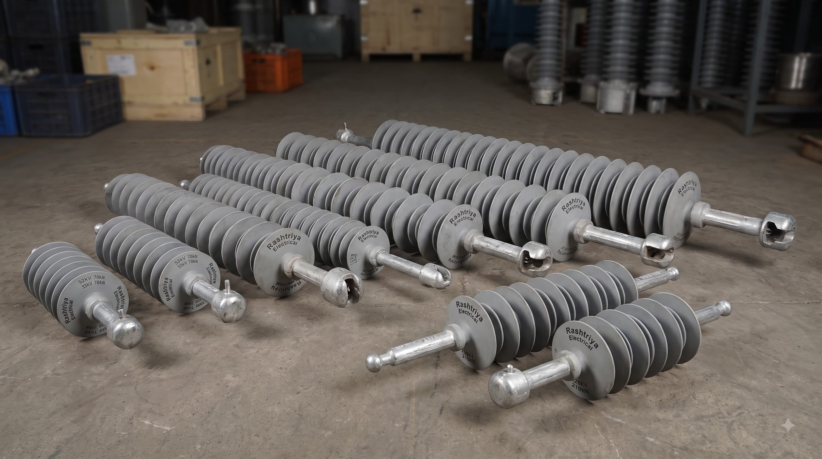
Rashtriya Electrical & Engg. Corporation offers Polymer Disc, Composite Suspension and Tension Insulators across multiple voltage classes, mechanical-strength classes and end-fitting configurations.
The current catalogue includes configurations across 11kV to 440kV and mechanical classes including 45kN, 70kN, 90kN, 120kN and 160kN, with different B&S, T&C, T&T and T&H arrangements depending on the individual product.
Explore the Polymer Disc Insulator range to compare recorded voltage, mechanical strength, connection type, creepage information, pricing and availability.
For a broader introduction to the different composite-insulator families, read our Polymer Insulators: Disc, Post & Pin Guide.
You can also explore:
- High Voltage Polymeric Insulators for the complete composite-insulator product group;
- Polymer Post Insulators for rigid line, bus and equipment-support applications;
- Polymer Pin Insulators for pin-mounted overhead-line conductor support;
- Polymer Long Rod Insulators for available long-rod line-insulator configurations.
Need Help Selecting the Correct Polymer Suspension or Tension Insulator?
Share your voltage requirement, mechanical strength, suspension/tension duty, creepage distance, end fitting, applicable standard and quantity with our team.
If available, attach your approved drawing or GTP.
Call +91 9311603492, email digital@rashtriyaelectrical.com, or contact Rashtriya Electrical for a technical and commercial enquiry.
Conclusion
A Polymer Disc Insulator is much more than a piece of insulating material between a conductor and a tower.
A correctly designed composite suspension or tension insulator combines:
FRP mechanical strength + polymer electrical insulation + silicone rubber sheds + suitable creepage distance + compatible end fittings + appropriate electrical withstand capability.
Its selection should therefore never be based on voltage alone.
For engineers and procurement teams, the most useful selection sequence is:
System voltage → mechanical duty → suspension/tension arrangement → end connection → creepage requirement → electrical withstand → dimensions → applicable standard.
Understanding these parameters makes it easier to compare products correctly, prepare an accurate technical enquiry and avoid selecting an insulator that matches only one part of the project requirement. The Polymer Disc Insulator range provides the current product-level specifications, pricing and availability.