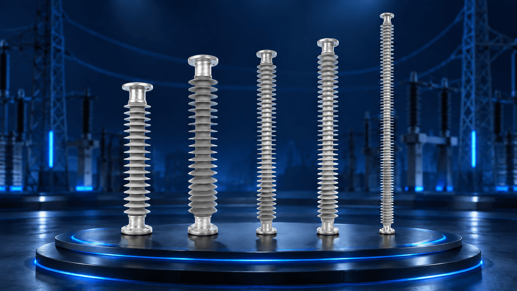
A high-voltage insulator does more than prevent electric current from reaching an earthed structure. In many installations, the insulator must also physically support a conductor, busbar or piece of electrical equipment while withstanding bending, compression, tension, vibration, wind and other mechanical forces.
A Polymer Post Insulator is designed for this combination of electrical insulation and rigid mechanical support.
Depending on the country, utility, manufacturer and application, these products may also be called Composite Post Insulators, Composite Polymer Post Insulators, Silicone Rubber Post Insulators, Solid-Core Post Insulators, Polymer Line Post Insulators, Composite Line Post Insulators, Polymer Station Post Insulators, Composite Station Post Insulators, Substation Post Insulators, Bus Post Insulators, Busbar Support Insulators or simply Support Insulators.
Despite the similar names, not every post insulator performs the same duty.
A line post installed on an overhead transmission structure has different mechanical and mounting requirements from a station post supporting substation equipment or a post supporting a rigid busbar.
For that reason, a post insulator should never be selected from voltage alone.
A technically useful selection process considers the complete installation, not one catalogue number in isolation.
Post insulator selection flow
- Application
- System voltage
- Mechanical load
- Creepage
- Insulation level
- Physical dimensions
- Mounting
- Applicable standard
This guide explains each of these parameters and shows how engineers, procurement teams, EPC contractors and electrical buyers can prepare a technically clear Polymer Post Insulator requirement.
For available configurations, see the Polymer Post Insulator range. For a broader comparison of composite technologies, start with the guide to polymer disc, post and pin insulators.
What Is a Polymer Post Insulator?
A Polymer Post Insulator is a generally rigid insulating support constructed to mechanically support an energized conductor or electrical apparatus while maintaining the required electrical separation from an earthed pole, tower, structure, equipment frame or foundation.
A typical solid-core composite post design consists of:
- an FRP/GRP load-bearing core;
- polymeric housing;
- silicone-rubber sheds;
- metallic end fittings;
- mechanically and environmentally controlled interfaces between these components.
IEC 62217:2025 covers general definitions, test methods and acceptance criteria for polymeric high-voltage insulators, including solid-core composite insulators used on overhead lines and in substations.
The central FRP core performs much of the structural work, while the external polymer housing provides environmental protection and external electrical insulation.
Unlike a suspension/tension insulator, where tensile force is usually a dominant mechanical consideration, a post insulator frequently operates under significant cantilever or bending load.
That difference is fundamental to correct product selection.
Why Does a Post Insulator Need Mechanical Strength?
Imagine a rigid busbar or conductor supported above a steel structure.
The conductor may apply force to the top of the insulator while the bottom fitting remains fixed to the structure.
This creates a bending moment.
Therefore a post insulator must not simply be electrically long enough for the voltage level. It must also possess the required mechanical capability for its installation.
Depending on the design, forces can arise from:
- conductor weight;
- busbar weight;
- wind;
- conductor tension;
- ice loading where applicable;
- short-circuit electrodynamic forces;
- equipment movement;
- vibration;
- seismic forces;
- installation geometry.
Composite station post insulators covered by IEC 62231 can be subjected to cantilever, torsional, tensile and compressive loads.
Main Types of Polymer Post Insulators
Overhead lines
Polymer Line Post
Supports an energized conductor on a pole or tower, commonly in vertical, horizontal or braced arrangements.
Substations
Polymer Station Post
Provides rigid support for energized substation equipment where combined mechanical duties can apply.
Rigid conductors
Bus Post Support
Supports a rigid busbar and must be checked against its mounting geometry and normal and short-circuit forces.
1. Polymer Line Post Insulator
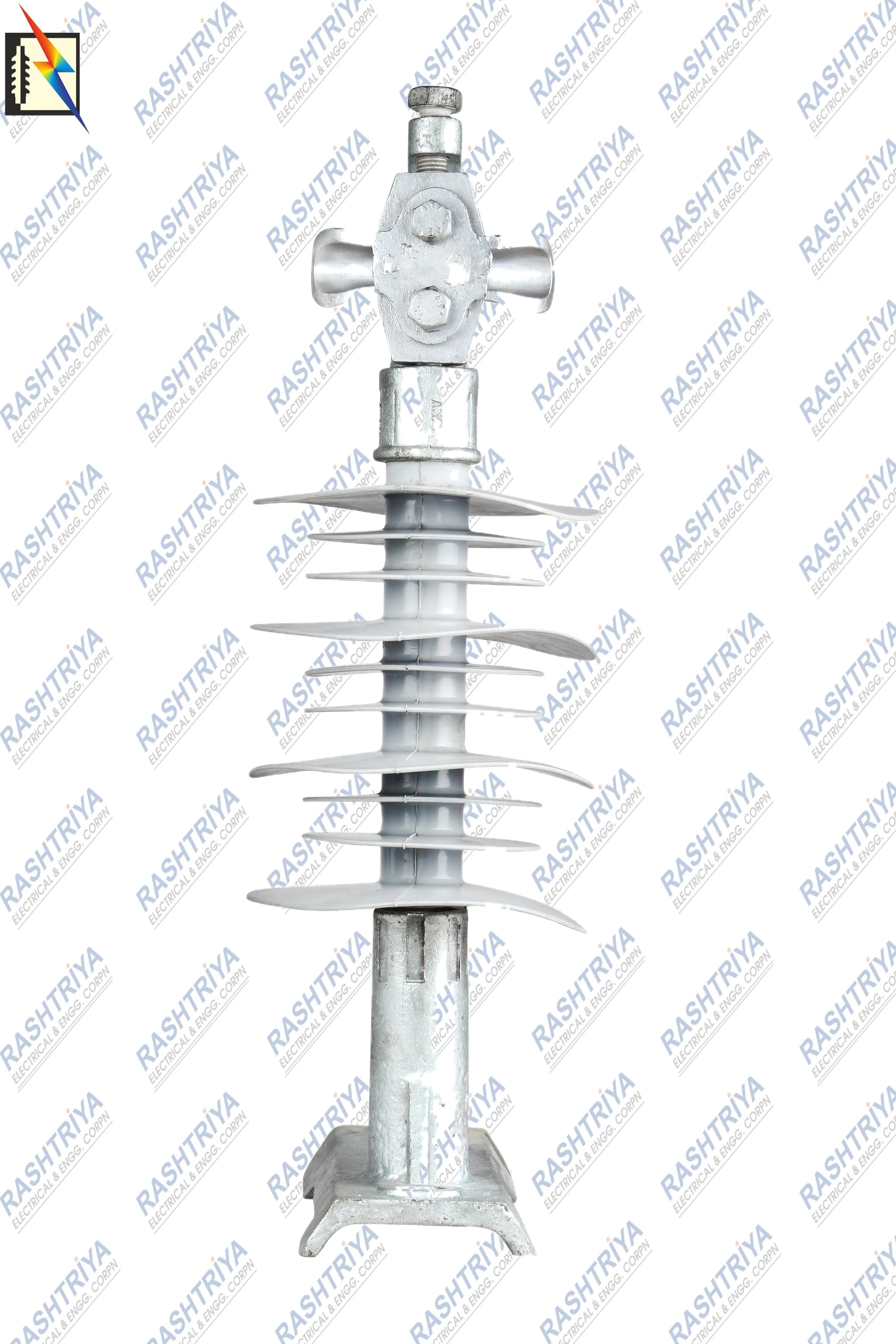
A Polymer Line Post Insulator is primarily designed to support an energized conductor on an overhead transmission or distribution structure.
It may also be searched as:
- Composite Line Post Insulator
- Silicone Rubber Line Post Insulator
- Composite Support Insulator
- Solid-Core Line Post Insulator
IEC 61952-1:2019 applies to composite line-post insulators used on AC overhead lines above 1,000 V and also recognizes similar designs used in substations and electric traction applications.
A line-post insulator can be installed in different orientations depending on the structure.
Typical configurations include:
Vertical Line Post
The insulator is installed approximately upright and supports the conductor above its mounting structure.
Horizontal Line Post
The post extends sideways from the supporting structure.
This configuration creates significant bending stress because conductor loads act at a distance from the post base.
Braced Line Post
A line-post insulator may form part of a more complex braced assembly where another insulating or mechanical element helps manage conductor loads.
Tie-Top Line Post
The conductor is retained at the line end using an appropriate tie arrangement.
Clamp-Top Line Post
A compatible conductor clamp is used instead of a conventional tie arrangement.
The correct configuration depends on the structure, conductor hardware, mechanical forces and utility specification.
2. Polymer Station Post Insulator
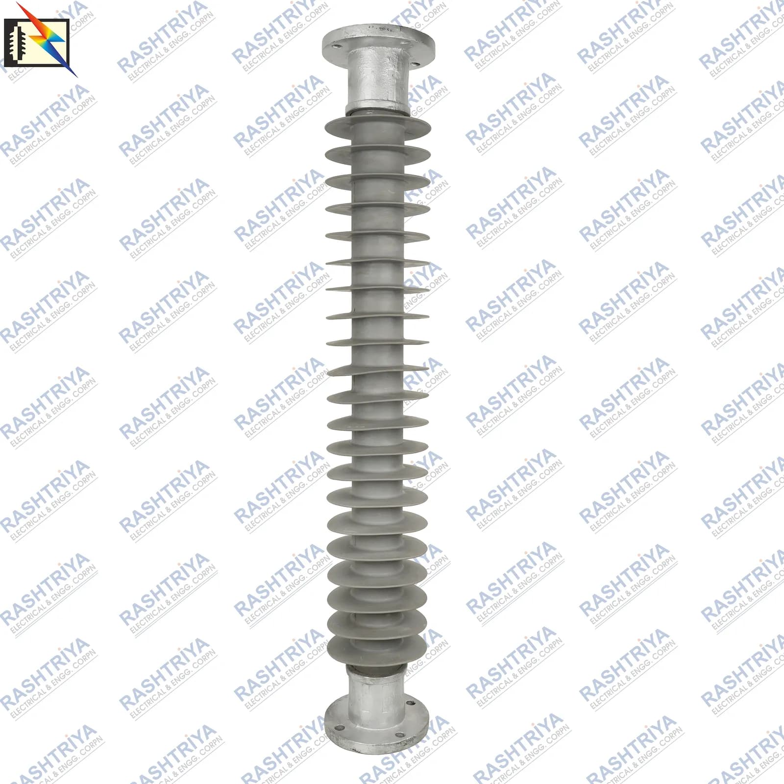
A Polymer Station Post Insulator is normally associated with substations, switchyards and high-voltage equipment where a rigid insulating support is required.
Typical applications include:
- isolators or disconnectors;
- rigid bus systems;
- switching equipment;
- equipment terminals;
- structural supports;
- other energized substation apparatus.
IEC 62231:2006 defines and addresses composite station-post insulators for substations within its stated AC voltage scope, while IEC 62231-1:2015 specifies principal dimensional, mechanical and electrical characteristics.
Station-post applications can involve combinations of:
Cantilever + Compression + Tension + Torsion
The required mechanical specification must therefore come from the actual equipment design rather than simply copying the rating of another post insulator.
3. Polymer Bus Post / Busbar Support Insulator
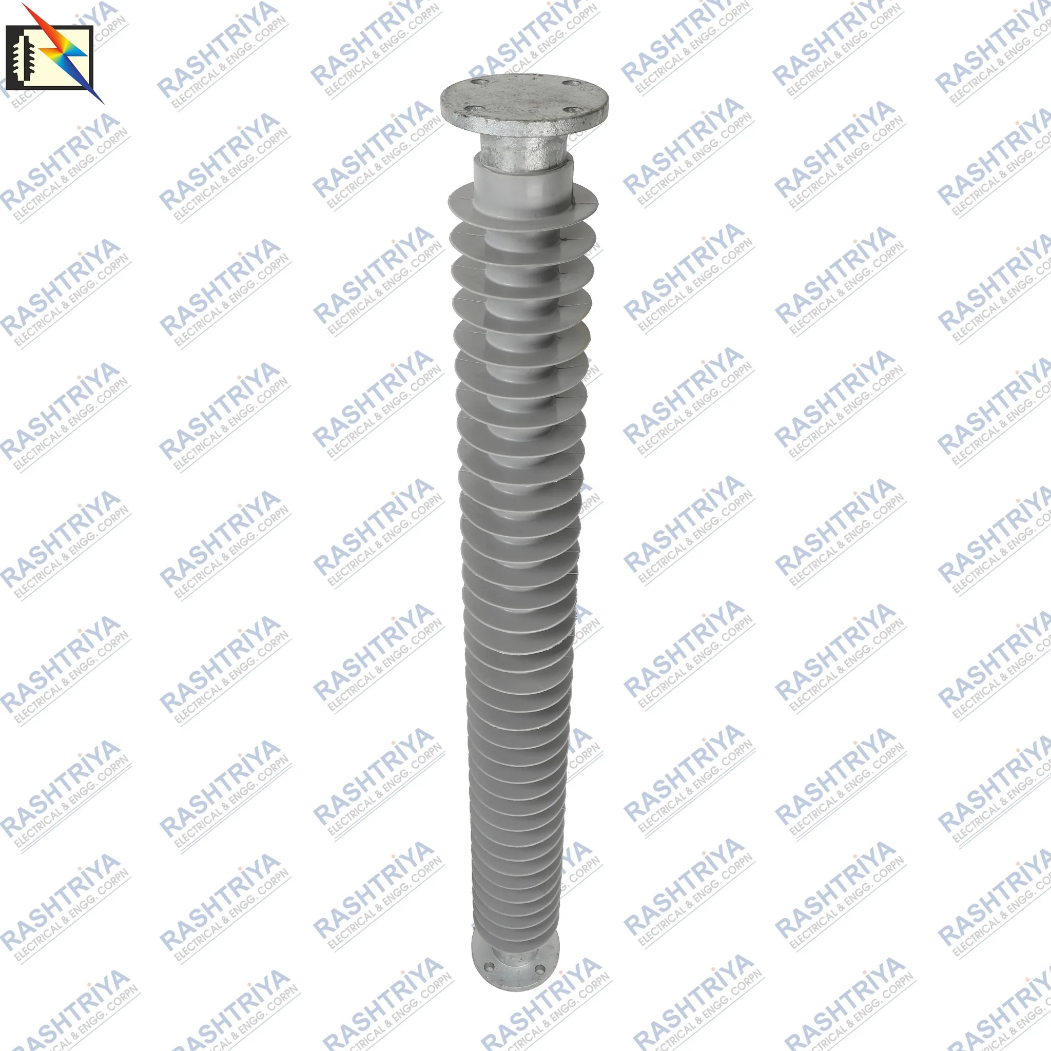
A Bus Post Insulator or Busbar Support Insulator supports an energized rigid busbar while maintaining electrical separation from the supporting steelwork or grounded structure.
It is an important commercial category, although “bus post” is better understood as a post-insulator application/configuration rather than necessarily a separate fundamental IEC insulator family.
Busbar installations can produce significant mechanical loading.
During a short circuit, electromagnetic forces between conductors can become much larger than their normal static weight.
For that reason, bus-post selection may involve:
- busbar size;
- support spacing;
- short-circuit current;
- conductor arrangement;
- cantilever strength;
- equipment height;
- mounting geometry;
- electrical clearance;
- insulation level.
The Rashtriya Electrical catalogue currently includes a dedicated 245kV Polymer Bus Post Insulator listing along with general and line-post products.
Line Post vs Station Post vs Bus Post
| Parameter | Line Post | Station Post | Bus Post / Bus Support |
|---|---|---|---|
| Primary purpose | Support overhead conductor | Support energized station equipment | Support rigid busbar |
| Typical location | Pole or tower | Substation / switchyard | Substation / switchyard |
| Important mechanical duty | Cantilever/bending | Cantilever, compression, tension and torsion as applicable | Cantilever plus busbar/electrodynamic load |
| Typical orientation | Vertical or horizontal | Usually rigid equipment mounting | Usually vertical/rigid support |
| Line-end arrangement | Tie, clamp, blade or compatible hardware | Equipment-specific | Busbar fitting |
| Major selection inputs | Voltage, line load, mounting, creepage | Equipment loads, insulation and dimensions | Bus forces, cantilever strength, dimensions and insulation |
The names should therefore describe the application, not just the appearance of the insulator.
Construction of a Composite Polymer Post Insulator
FRP / GRP Core Rod
At the centre of a typical solid-core composite post insulator is a fibre-reinforced resin rod.
It is commonly referred to as:
FRP — Fibre Reinforced Polymer
or
GRP — Glass Reinforced Plastic
Glass fibres embedded in a resin matrix provide high mechanical strength with relatively low weight.
For line-post applications, the core has to resist significant bending loads.
IEC 61952 describes composite line-post insulators as having a load-bearing cylindrical insulating core generally made from fibres—usually glass—in a resin matrix, together with polymer housing and permanently attached fittings.
Core diameter may influence mechanical design, but it should not be used alone to infer the strength of an insulator.
The complete tested assembly matters.
Silicone Rubber Housing
The FRP core is surrounded by an external polymer housing.
Silicone rubber is widely used for composite high-voltage insulation because it provides:
- electrical insulation;
- environmental protection for the core;
- flexible shed geometry;
- hydrophobic surface behaviour.
Hydrophobicity means that water tends to form droplets instead of spreading easily into a continuous film.
This can be useful when an insulator operates in wet or contaminated outdoor conditions.
However, polymer performance is influenced by material formulation, ageing, contamination, electric-field stress and environmental exposure. It should therefore not be described as permanently maintenance-free.
IEC 62217:2025 includes updated provisions concerning hydrophobicity-transfer materials, housing materials, core materials, interfaces and end-fitting connections.
Silicone Rubber Sheds
The projecting profiles around the post are called sheds.
Their role is not merely decorative.
Sheds help increase the surface path between energized and grounded ends and influence wet and pollution performance.
Important shed-related variables can include:
- shed diameter;
- shed spacing;
- alternating or equal shed profiles;
- overhang;
- housing diameter;
- number of sheds;
- installation orientation.
A product should not be judged simply by saying:
More sheds = better insulator.
The complete insulation design is more important than shed count alone.
Metallic End Fittings
Metallic fittings connect the composite insulating body to external structures, conductors or equipment.
Depending on the approved product design and client specification, suitable fitting materials may include:
- SG Iron / Ductile Iron;
- Forged Steel;
- Malleable Cast Iron;
- other engineered metallic materials.
Important fitting parameters include:
- top connection;
- bottom connection;
- flange dimensions;
- PCD;
- hole diameter;
- number of mounting holes;
- fitting orientation;
- galvanizing/corrosion protection;
- mechanical strength.
The exact material should be stated from the approved product drawing rather than assumed from appearance.
Interfaces and Bonding
The interfaces between the core, housing and end fittings are critical to sealing and mechanical integrity. Their design should limit moisture ingress and maintain reliable load transfer without assuming any unverified proprietary bonding method.
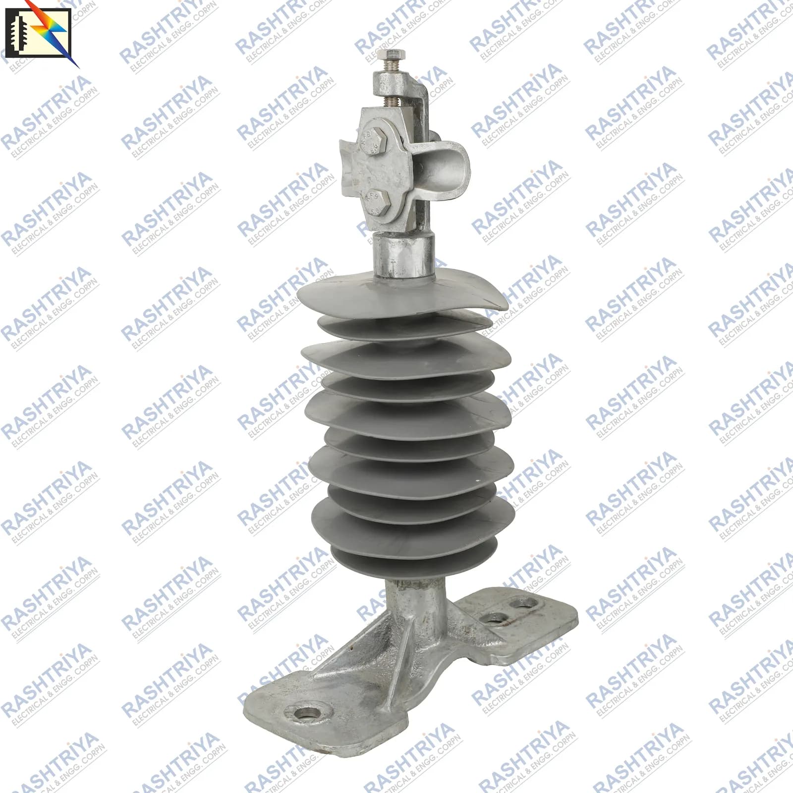
What Is Cantilever Strength?
Cantilever strength is one of the most important mechanical terms associated with post insulators.
A cantilever force acts transverse to the main axis of the post and creates bending stress.
Consider a simple example.
If a horizontal force F acts at a distance L from the fixed base, the first-order bending moment at the base is:
For example, if an illustrative 1 kN horizontal force acts 1.0 m above the fixed base:
M = 1 × 1 = 1 kN·m
If the same force acts 2 m above the base:
M = 1 × 2 = 2 kN·m
The force did not change, but the bending moment doubled.
This demonstrates why post height and load application point matter.
A simple kN comparison cannot replace the actual structural calculation.
SCL vs MDCL: What Do They Mean?
This distinction is particularly important.
SCL — Specified Cantilever Load
Specified Cantilever Load is the cantilever load that the insulator is required to withstand under the prescribed test conditions.
IEC 62231-1 defines SCL in this way for station-post insulators. IEC line-post documents likewise use SCL as an important mechanical characteristic.
SCL should not automatically be treated as the everyday working load.
MDCL — Maximum Design Cantilever Load
Maximum Design Cantilever Load represents the load level above which damage to the insulator/core begins to occur and therefore forms an upper design limit for service loading according to the relevant design definition.
IEC 61952-1 distinguishes MDCL from SCL, and notes that a manufacturer's recommended working cantilever load may be expressed through MDCL or RCL and can be substantially below SCL.
That difference should be respected during equipment design.
What About RCL?
Some specifications use:
RCL — Reference Cantilever Load
IEC 61952-1 identifies RCL with North American practice for defining maximum admissible working load.
This terminology is especially useful when reviewing international tenders because a buyer may provide SCL, MDCL or RCL depending on the standard and region being used.
Always ask which definition applies.
| Parameter | Meaning |
|---|---|
| SCL | Specified test/load characteristic under the applicable standard |
| MDCL | Design limit related to the onset of damage |
| RCL | Reference or working-load concept used in some specifications |
Polymer Post Insulator Mechanical Ratings
The Rashtriya Electrical Post Insulator catalogue currently includes product records with mechanical classes such as:
| Catalogue Mechanical Class | Typical Interpretation |
|---|---|
| 5kN | Post configuration with specified recorded mechanical class |
| 6kN | Intermediate mechanical class |
| 8kN | Higher recorded mechanical class |
| 10kN | Higher cantilever/mechanical requirement |
Catalogue mechanical classes — select by load and application
- 5kN
- 6kN
- 8kN
- 10kN
These are catalogue/product classes—not a rule that every voltage level is available in every mechanical configuration.
For example, the current catalogue includes 66–72kV products in 8kN and 10kN variants.
Always verify what the kN value represents on the approved drawing or GTP.
A Basic Cantilever Selection Concept
For preliminary understanding, suppose several horizontal forces act on equipment supported by a post.
The total base moment can be approximated as:
Mtotal = F₁L₁ + F₂L₂ + F₃L₃ + …
If an equivalent force is required at a chosen reference height Lr:
Feq = Mtotal / Lr
This is useful for understanding the mechanics, but it is not a final insulator-selection calculation.
An engineering design can also require:
- load combinations;
- safety factors;
- short-circuit forces;
- wind loading;
- seismic loading;
- conductor tension;
- torsional effects;
- dynamic effects;
- manufacturer load curves;
- applicable standard requirements.
The selected post should therefore be verified against the project structural calculation and manufacturer data.
Creepage Distance in a Polymer Post Insulator
Creepage distance is the shortest path—or sum of shortest paths—along the insulating surface between conductive parts that normally have operating voltage between them.
It should not be confused with straight-line air distance.
For an outdoor post insulator, creepage design is particularly relevant under contamination such as:
- industrial pollution;
- dust;
- salt spray;
- coastal deposits;
- agricultural contamination;
- moisture combined with surface contamination.
IEC TS 60815-1:2025 provides the general pollution-selection framework, while IEC TS 60815-3:2025 specifically addresses polymer insulators for AC systems. The current approach considers site pollution severity, shed profile, dimensions, altitude, mounting and material characteristics rather than selecting creepage from voltage alone.
An Important Difference: SCD vs USCD
This is a common source of specification errors.
Modern IEC pollution-selection terminology uses:
USCD — Unified Specific Creepage Distance
Conceptually:
USCD = Total Creepage Distance / RMS Highest Operating Voltage Across the Insulator
It is normally expressed in mm/kV.
IEC TS 60815-1:2025 specifically states that the voltage basis is the RMS highest operating voltage across the insulator.
For a phase-to-earth insulator on a three-phase system, that voltage basis is commonly related to the phase-to-earth value rather than blindly using the line-to-line number.
This is important because older “specific creepage distance” conventions and modern USCD terminology can differ by a factor of √3 for line-to-earth insulation.
Therefore a statement such as:
“25 mm/kV creepage”
is incomplete unless the specification clearly identifies:
- the creepage definition;
- the voltage basis;
- applicable standard;
- system configuration.
The same caution applies to values such as 31 mm/kV or 35 mm/kV.
Basic Creepage Calculation
Once the required USCD and voltage basis have been established according to the project and pollution assessment, a simplified dimensional relationship is:
This is only a starting relationship.
IEC TS 60815-3:2025 includes consideration of corrections for factors such as insulator geometry, altitude, profile, size, orientation and hydrophobicity-transfer material behaviour.
Therefore:
Do not design a post insulator by multiplying a memorized mm/kV number by nominal voltage.
Use the project specification and applicable IEC methodology.
Creepage Values in the Catalogue
The Rashtriya Electrical catalogue contains products with different creepage values.
For example, a current 33kV 10kN Polymer Line Post listing records 1100 mm creepage distance, while 132/145kV catalogue records include product-specific 3625 mm and 4495 mm variants.
Such values should be treated as individual product specifications, not universal requirements for the voltage class.
Creepage Distance vs Dry Arcing Distance
These parameters are often confused.
Creepage Distance
The path measured along the insulating surface.
Dry Arcing Distance
The shortest relevant air path between energized and grounded conductive parts under the defined geometry.
Overall Height
The physical end-to-end dimensional height of the insulator.
Electrical Clearance
The required separation through air within the complete installation.
An insulator can have a large creepage distance because its sheds create a long surface path while having a much shorter dry arcing distance.
Both parameters matter, but for different reasons.
What Is PCD in a Post Insulator?
PCD means Pitch Circle Diameter.
It is the diameter of the imaginary circle passing through the centres of equally spaced mounting holes.
PCD is extremely important when a post insulator is attached to:
- a steel structure;
- equipment base;
- isolator frame;
- bus-support structure;
- replacement mounting position.
Two post insulators can have the same voltage and mechanical strength yet be mechanically incompatible because their PCD or hole pattern differs.
What Should Be Specified Along With PCD?
Do not provide only:
PCD = 76 mm
A complete mounting requirement should ideally identify:
PCD + Number of Holes + Hole Diameter + Flange Diameter + Fitting Orientation
This greatly reduces installation mismatch.
Important Dimensions of a Polymer Post Insulator
Overall Height
Influences phase-to-earth clearance, busbar elevation, equipment geometry, replacement compatibility and insulation design.
Shed Diameter
Describes the external diameter across a shed and should not be confused with PCD.
Core Diameter
Refers to the load-bearing composite core, but does not alone define the mechanical characteristic of a line-post insulator.
Flange Diameter
Describes the overall diameter of the mounting flange.
Pitch Circle Diameter
Defines the circle through mounting-hole centres and affects compatibility with the supporting structure.
Bolt-Hole Diameter
Determines compatible fastener size and must be considered together with PCD and hole quantity.
Therefore a product specification should avoid the ambiguous word:
Diameter: 105 mm
Instead write exactly:
- Shed Diameter;
- FRP Core Diameter;
- Flange Diameter;
- PCD;
- Bolt-Hole Diameter.
Power-Frequency Dry Withstand Voltage
A power-frequency dry withstand voltage is a specified AC test-voltage level that the insulation must withstand under defined dry laboratory conditions without disruptive discharge according to the relevant test procedure.
It is a withstand value, not the voltage at which flashover is expected.
That distinction matters.
Power-Frequency Wet Withstand Voltage
Outdoor insulation must also operate when wet.
A power-frequency wet withstand test evaluates the insulation under standardized wet conditions.
Water affects the external electric field and surface conduction, so wet insulation performance can differ significantly from dry performance.
High-voltage AC test methodology is governed by standards such as IEC 60060-1:2025, while the product-specific insulator standard determines which tests and acceptance values apply.
Withstand Voltage vs Flashover Voltage
These terms should not be used interchangeably.
Withstand Voltage
A specified voltage that the insulation is required to survive under a defined test procedure without unacceptable disruptive discharge.
Flashover Voltage
A voltage at which an external disruptive discharge occurs across the insulation or surrounding air path under specified test conditions.
Therefore:
“Wet withstand = X kV”
and
“Wet flashover = X kV”
are not equivalent specifications.
Do not copy a flashover value into a withstand field.
Lightning Impulse Withstand Voltage
Power systems can experience fast transient overvoltages due to lightning and switching events.
A lightning impulse withstand voltage therefore represents another key insulation characteristic.
The standard lightning impulse waveform used in high-voltage testing is conventionally described as approximately 1.2/50 μs.
IEC 60060-1:2025 defines high-voltage test techniques for AC, DC and impulse testing, while IEC 60071-1:2019 establishes principles for insulation coordination and selecting standardized withstand levels.
The required impulse level should come from the approved insulation-coordination or project specification.
What Are BIL, CFO and CIFO?
Different markets use somewhat different terminology.
BIL
BIL — Basic Lightning Impulse Insulation Level / rated lightning impulse withstand concept
Line-post classification under IEC 61952-1 uses minimum lightning impulse withstand voltage classes associated with standardized impulse levels.
CFO — Critical Flashover Voltage
In specifications using CFO terminology, Critical Flashover Voltage generally refers to an impulse voltage associated with approximately a 50% probability of flashover for self-restoring external insulation under the specified conditions.
Positive- and negative-polarity values can differ.
CFO is therefore a statistical flashover characteristic rather than the same quantity as a guaranteed withstand level.
CIFO — Critical Impulse Flashover
Some North American procurement specifications use the abbreviation CIFO for critical impulse flashover and list separate positive and negative values.
For example, utility specifications for composite line-post insulators can explicitly request minimum positive and negative CIFO values alongside dry/wet flashover and arcing distance.
Therefore a customer specification containing:
- positive CIFO;
- negative CIFO;
- impulse withstand;
should not have those fields merged into one value.
Positive vs Negative Impulse
The polarity of an impulse can influence external discharge development around an insulator.
Consequently, positive and negative critical impulse flashover values may be different.
If a tender or GTP asks for both, provide verified test/design values independently.
Do not derive one polarity from the other using an assumed percentage.
Voltage Rating vs Highest System Voltage
Another common specification problem is treating all voltage terms as identical.
For example:
33kV system voltage
does not necessarily mean every related test and equipment value is simply “33kV.”
A project may separately specify:
- nominal/rated system voltage;
- highest system/equipment voltage;
- power-frequency withstand;
- lightning impulse withstand;
- creepage requirement.
IEC 60071-1 specifically associates insulation-coordination withstand levels with the highest voltage for equipment rather than treating nominal voltage as the only insulation parameter.
Typical Polymer Post Insulator Voltage Classes
The current Rashtriya Electrical catalogue includes post-insulator product names across classes such as:
11kV • 33/36kV • 66/72kV • 132/145kV • 220/245kV • 440kV
Actual values vary by individual product.
Do not interpret this as meaning every mechanical, creepage and electrical configuration is available at each voltage.
50Hz vs 60Hz Operation
Composite line-post standards cover AC power-frequency systems, and IEC 61952-1 applies within its specified frequency range up to 100 Hz.
Most utility systems commonly operate at either:
50Hz or 60Hz
depending on the country.
A product should nevertheless be checked against the customer's specified system and test standard rather than advertising “50/60Hz” as proof of universal compatibility.
What About HVDC Post Insulators?
Composite polymer technology can also be used in DC high-voltage applications, but DC insulation design should not simply reuse AC creepage and field-design assumptions.
IEC 62217:2025 covers polymeric insulators within its stated AC and DC voltage scope, while the IEC 60815 series handles pollution selection differently for AC and DC systems.
Therefore an AC catalogue post insulator should not automatically be described as an HVDC product unless the design, testing and application support that claim.
Mounting Configurations
Vertical / Upright
The post stands approximately vertically above its base for suitable bus, equipment or line-support applications.
Horizontal Line Post
The post extends sideways from the structure, making cantilever and bending loads especially important.
Gain Base
Interfaces with compatible structure hardware in certain line-post applications.
Flat / Flange Base
Provides the rigid bolted base commonly used for station and bus-post applications.
Clamp Top
Uses a compatible conductor clamp at the line end.
Tie Top
Retains the conductor with the specified tie arrangement.
Blade / Equipment Fitting
Connects to compatible line or apparatus hardware defined by the approved drawing.
Clamp top and tie top are conductor-end configurations—not separate fundamental insulator types.
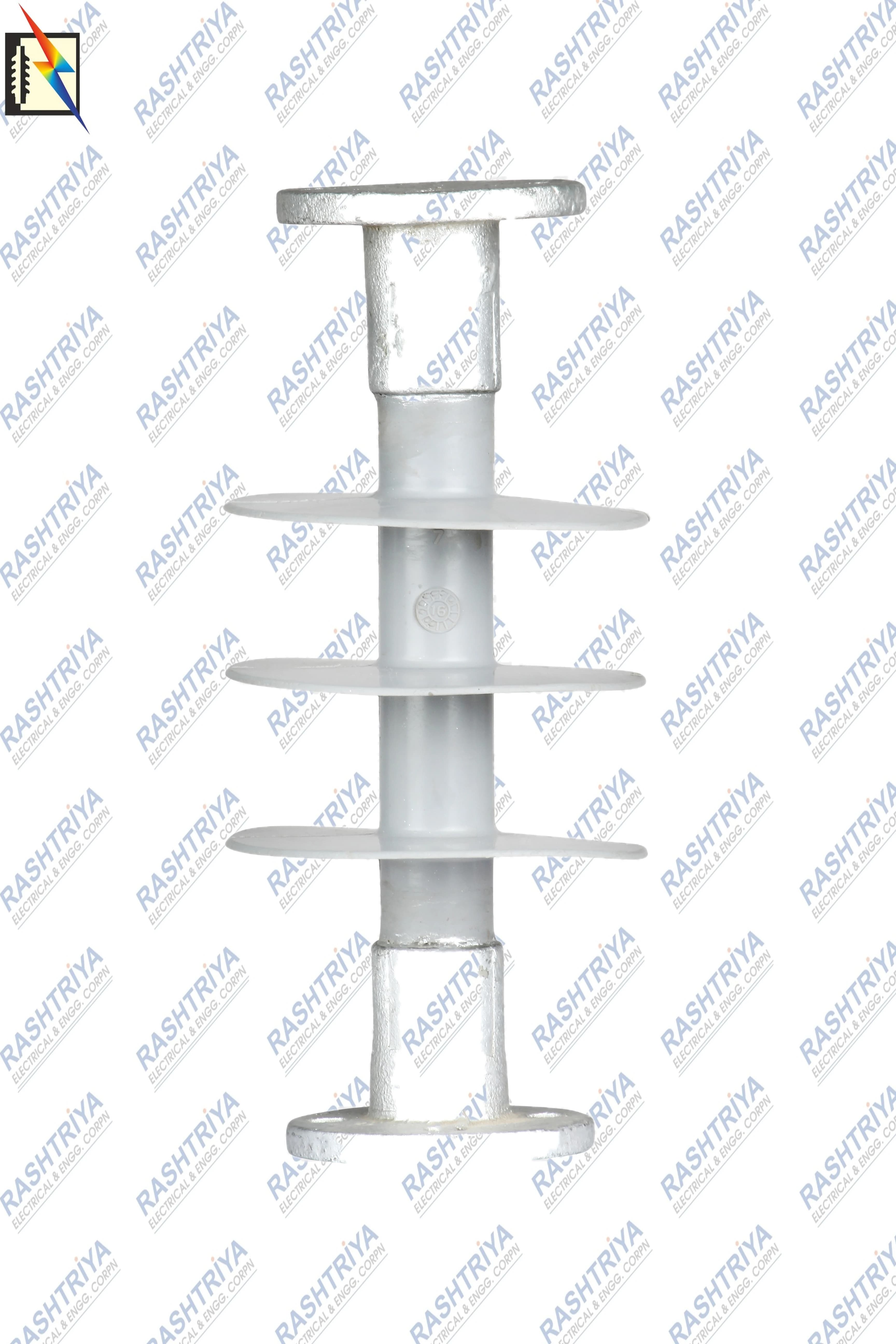
Polymer Post vs Porcelain Post Insulator
| Parameter | Composite Polymer Post | Porcelain Post |
|---|---|---|
| Main insulating structure | FRP core + polymer housing | Ceramic porcelain body |
| Weight | Generally lighter | Generally heavier |
| External housing | Often silicone rubber | Porcelain |
| Surface property | Silicone designs can exhibit hydrophobicity | Porcelain surface is generally hydrophilic unless treated |
| Mechanical behaviour | Composite structural design | Brittle ceramic structure |
| Handling | Lower weight may simplify handling | Greater weight and brittle material require appropriate handling |
| Ageing considerations | Housing, interfaces, seals, core and electric-field effects | Ceramic body, cement/fittings and mechanical integrity |
| Selection | Electrical + mechanical + environmental | Electrical + mechanical + environmental |
Neither technology should be declared universally “best.”
The correct comparison depends on:
- application;
- mechanical load;
- environmental condition;
- utility experience;
- required dimensions;
- testing;
- lifecycle requirements.
Advantages of Composite Polymer Post Insulators
When properly designed for their application, composite post insulators can provide:
Lower Weight
Composite construction can significantly reduce handling mass compared with equivalent conventional ceramic designs.
Strength-to-Weight Ratio
The FRP core can provide substantial mechanical capability relative to its weight.
Hydrophobic Silicone Surface
Suitable silicone-rubber formulations can provide hydrophobic surface behaviour useful for outdoor insulation.
Flexible Shed Design
Polymer housing can be engineered with shed profiles suited to specific insulation designs.
Multiple Mounting Options
Different line-end and structure-end fittings can be provided according to application.
Reduced Brittle-Shell Behaviour
The polymer housing does not behave like a brittle ceramic shell, although the core, seals and fittings must still be protected from damage.
Factors That Affect Long-Term Performance
Composite does not mean immune to ageing.
Important stresses can include:
- UV exposure;
- electric-field concentration;
- corona;
- dry-band arcing;
- tracking;
- erosion;
- pollution;
- moisture;
- temperature cycling;
- mechanical fatigue;
- fitting corrosion;
- loss of sealing integrity;
- interface degradation.
IEC 62217:2025 contains requirements addressing housing materials, interfaces, core materials and end-fitting connections, reflecting the importance of these areas to polymer-insulator reliability.
Electric-Field Control and Corona Rings
At higher voltage classes, electric-field concentration near energized fittings can become important.
Depending on the insulator geometry, voltage and manufacturer design, field-control devices such as corona or grading rings may be required.
Their purpose can include:
- controlling electric-field concentration;
- reducing corona activity;
- reducing localized electrical stress on polymer housing.
IEC 62217:2025 specifically highlights the need for electric-field control consideration for polymeric AC insulators.
Whether a ring is required, along with its diameter and position, must come from the approved product design.
Do not add a ring solely because another manufacturer's visually similar insulator uses one.
How to Select a Polymer Post Insulator
Selection review sequence
- Identify application
- Confirm system voltage
- Confirm highest system voltage
- Determine mechanical / SCL requirement
- Confirm creepage / USCD
- Confirm electrical withstand
- Confirm dimensions
- Confirm PCD and bolt pattern
- Confirm mounting
- Confirm applicable standard
- Review drawing / GTP
Step 1 — Identify the Application
First establish whether the insulator is for:
- overhead line support;
- station equipment;
- busbar;
- isolator/disconnector;
- replacement of an existing unit;
- another engineered support application.
Application determines the mechanical loading philosophy.
Step 2 — Confirm System Voltage
Provide:
- nominal voltage;
- highest system/equipment voltage;
- AC or DC.
Do not provide only “33kV” where the project specification contains more complete information.
Step 3 — Determine Mechanical Loads
For line-post applications, confirm:
- SCL where specified;
- MDCL/RCL where relevant;
- conductor load;
- line geometry;
- wind and other structural loading.
For station or bus-support applications, also consider:
- compression;
- tension;
- torsion;
- equipment forces;
- short-circuit forces.
Step 4 — Establish Creepage Requirement
Provide either:
- required total creepage distance;
- required USCD and voltage basis;
- pollution/site classification;
- exact utility specification.
Avoid an ambiguous statement such as:
“Need 25 mm/kV.”
State what the number means.
Step 5 — Confirm Insulation Levels
Depending on the project, provide:
- dry power-frequency withstand;
- wet power-frequency withstand;
- lightning impulse withstand/BIL;
- switching impulse requirement where relevant;
- CFO/CIFO if required by the governing specification.
Step 6 — Confirm Physical Dimensions
Important dimensions may include:
- overall height;
- dry arcing distance;
- shed diameter;
- core diameter if required;
- flange diameter;
- PCD;
- bolt-hole diameter;
- hole quantity.
Step 7 — Confirm Mounting
Specify:
- vertical;
- horizontal;
- gain base;
- flange/base;
- clamp top;
- tie top;
- blade/equipment fitting;
- other drawing-specific configuration.
Step 8 — Confirm Applicable Standards
The applicable standard depends on product type and project.
Relevant IEC documents can include:
- IEC 61952 / IEC 61952-1 for composite line-post applications;
- IEC 62231 / IEC 62231-1 for solid-core composite station-post applications within their stated scopes;
- IEC 62217 for general polymer-insulator tests and materials;
- IEC TS 60815-1 and IEC TS 60815-3 for pollution selection of outdoor AC polymer insulation;
- IEC 60071-1 for insulation coordination;
- IEC 60060-1 for high-voltage test techniques.
The edition specified in the tender, GTP or contract should govern unless formally amended.
Polymer Post Insulator Selection Checklist
| Requirement | Information to Provide |
|---|---|
| Application | Line / station / bus support / equipment |
| Nominal system voltage | e.g. 33kV |
| Highest system voltage | e.g. project-specified Um |
| AC/DC | System type |
| Frequency | 50Hz / 60Hz where relevant |
| SCL | Required specified cantilever load |
| MDCL/RCL | Where required |
| Compression/tension/torsion | Station/equipment applications where relevant |
| Creepage | Total creepage or defined USCD requirement |
| Pollution environment | Site/utility requirement |
| Overall height | Required dimension |
| Dry arcing distance | If specified |
| PCD | Mounting requirement |
| Bolt holes | Quantity + diameter |
| Top fitting | Clamp / tie / blade / flange / drawing |
| Bottom fitting | Base / flange / gain / drawing |
| Dry PF withstand | Project value |
| Wet PF withstand | Project value |
| Lightning impulse withstand | Project value |
| CFO/CIFO | If required |
| Standard | IEC / IS / ANSI/NEMA / utility specification |
| Quantity | Required pieces |
| Drawing / GTP | Strongly recommended |
Example of a Better Technical Enquiry
Weak enquiry
Voltage only
“Send price for 33kV post insulator.”
Better enquiry
Defined requirement
“Required: 33kV Polymer Line Post Insulator, 10kN mechanical requirement, specified creepage distance, horizontal/vertical mounting as per drawing, required PCD and bolt pattern, applicable withstand levels and utility specification. Quantity: ___.”
This allows the manufacturer to compare the actual requirement with the appropriate catalogue or custom configuration.
Common Polymer Post Insulator Selection Mistakes
Selecting by Voltage Alone
Two 33kV post insulators can have completely different mechanical and dimensional characteristics.
Confusing kN With Electrical Rating
A 10kN post insulator does not mean 10kA or 10kV.
kN is a unit of mechanical force.
Treating SCL as Normal Working Load
SCL is a specified test-related mechanical characteristic. Working/design limits need to follow the relevant load philosophy and manufacturer/project data.
Assuming Every mm/kV Value Uses the Same Definition
Old specific creepage terminology and current IEC USCD terminology can use different voltage bases.
Always state the standard and voltage basis.
Confusing Creepage With Arcing Distance
Creepage follows the insulating surface.
Arcing distance is through air.
Writing Only “Diameter”
State whether the dimension is:
- PCD;
- shed diameter;
- FRP core diameter;
- flange diameter;
- bolt-hole diameter.
Confusing Withstand and Flashover
They are not interchangeable test quantities.
Assuming Every Polymer Post Is Suitable for HVDC
AC and DC external-insulation design require different considerations.
Copying Another Manufacturer's Dimensions
A visually similar post does not guarantee mechanical, electrical or mounting compatibility.
Selecting by Image Alone
Product appearance cannot establish voltage, cantilever, creepage, insulation-level or mounting compatibility. Select from verified specifications and drawings.
Relevant IEC Standards
IEC 61952:2008
IEC 61952:2008 covers composite line-post insulators for AC overhead-line systems within its scope, including definitions, test methods and acceptance criteria.
IEC 61952-1:2019
IEC 61952-1:2019 defines line-post terminology, standardized fittings/designations and characteristics including MDCL and lightning impulse withstand classification.
IEC 62231:2006
IEC 62231:2006 addresses composite station-post insulators within its stated AC substation voltage scope and covers definitions, test methods and acceptance criteria.
IEC 62231-1:2015
IEC 62231-1:2015 specifies principal dimensional, mechanical and electrical characteristics for composite station-post insulators.
IEC 62217:2025
IEC 62217:2025 provides general definitions, test methods and acceptance criteria for polymeric HV insulators, including solid-core composite designs.
IEC TS 60815-1:2025
IEC TS 60815-1:2025 provides the overall framework for selecting external high-voltage insulation for polluted conditions and defines concepts including site pollution severity and USCD.
IEC TS 60815-3:2025
IEC TS 60815-3:2025 specifically addresses pollution selection and dimensioning of outdoor polymer insulators for AC systems.
IEC 60071-1:2019
IEC 60071-1:2019 provides insulation-coordination principles and standardized withstand-level concepts for AC systems above 1kV.
IEC 60060-1:2025
IEC 60060-1:2025 provides general high-voltage test terminology and requirements for AC, DC and impulse-voltage testing.
Frequently Asked Questions
What is a Polymer Post Insulator?
A Polymer Post Insulator is a rigid composite insulating support used to electrically isolate and mechanically support energized conductors, busbars or electrical equipment. Typical construction uses an FRP core, polymer/silicone-rubber housing and metallic end fittings.
What is another name for a Polymer Post Insulator?
Depending on application and market, common terms include Composite Post Insulator, Silicone Rubber Post Insulator, Solid-Core Post Insulator, Composite Line Post Insulator, Station Post Insulator, Substation Post Insulator and Busbar Support Insulator.
What is the difference between a Line Post and Station Post Insulator?
A line-post insulator normally supports a conductor on an overhead line structure. A station-post insulator provides rigid insulation and support for equipment or conductors within substations and switchyards. Their mechanical duties, fittings and standards can differ.
Is a Bus Post a separate type of insulator?
“Bus Post” is a useful commercial/application term for a post insulator supporting an energized busbar. It is often better understood as a bus-support post/station-post application rather than a completely independent material family.
What does 10kN mean on a post insulator?
10kN describes a mechanical force characteristic associated with the insulator's specification. The exact meaning—such as SCL or another rated mechanical characteristic—should be confirmed from its GTP or drawing.
What is SCL?
SCL means Specified Cantilever Load. It represents the cantilever load that the insulator can withstand under the prescribed test conditions.
What is MDCL?
MDCL means Maximum Design Cantilever Load. It represents a design limit associated with the onset of damage and should not be exceeded in service according to the applicable definition/design.
Is SCL the working load?
Not automatically. SCL is a specified test characteristic. The permitted working/design load can be lower and must follow the relevant standard, manufacturer and project specification.
What is creepage distance?
Creepage distance is the path measured along the insulating surface between conductive parts that normally have voltage between them.
What does mm/kV creepage mean?
It expresses creepage relative to a defined voltage basis. Modern IEC terminology uses Unified Specific Creepage Distance, or USCD. The applicable voltage basis and standard must be stated because different conventions can produce different numerical values.
What is dry arcing distance?
Dry arcing distance represents the relevant shortest air path between conductive ends under the specified geometry. It is different from creepage distance, which follows the surface.
What is PCD?
PCD means Pitch Circle Diameter—the diameter of the imaginary circle through the centres of mounting bolt holes.
What is dry power-frequency withstand voltage?
It is the specified AC voltage the insulator must withstand under defined dry test conditions without unacceptable disruptive discharge.
What is wet power-frequency withstand voltage?
It is the corresponding withstand requirement under standardized wet conditions.
What is lightning impulse withstand voltage?
It is the specified impulse-voltage level the insulation must withstand according to the applicable high-voltage test and product requirements.
What is CFO or CIFO?
CFO generally means Critical Flashover Voltage, a statistical impulse-flashover characteristic commonly associated with approximately 50% flashover probability under specified conditions. Some specifications use CIFO, or Critical Impulse Flashover, and may state separate positive and negative values.
Are positive and negative impulse values the same?
Not necessarily. External flashover characteristics can depend on polarity, so specifications may state different positive and negative impulse values.
Can Polymer Post Insulators be used in polluted areas?
Yes, when the external-insulation design is properly selected for the actual pollution environment. Creepage, profile, dimensions, orientation, material behaviour and site conditions all need to be considered.
Is 25 mm/kV suitable for every post insulator?
No. A creepage figure such as 25 mm/kV should never be applied universally without knowing the creepage definition, voltage basis, pollution conditions and governing specification.
Can a Line Post Insulator be mounted horizontally?
Yes, suitable composite line-post designs can be installed horizontally. The cantilever loading and fitting arrangement must be designed for that installation.
What details should I provide before requesting a quotation?
Provide the application, voltage, highest system voltage, mechanical/cantilever requirement, creepage, height, PCD, bolt pattern, top/bottom fittings, electrical withstand values, standard and quantity. A GTP or drawing is strongly recommended.
Explore Polymer Post Insulators
Rashtriya Electrical & Engg. Corporation maintains a Polymer Post Insulator catalogue covering multiple line-post, general post and bus-support configurations across different voltage and mechanical classes.
The commercial category should be used to compare actual:
Product → Voltage → Mechanical Rating → Creepage → Recorded Specifications → Price / Availability → Enquiry
For actual products, specifications and commercial availability, explore the Polymer Post Insulator range.
For a broader introduction to composite insulation technologies, read Polymer Insulators: Disc, Post & Pin Types, Construction, Ratings and Applications.
Engineers comparing suspension or tension applications can also refer to the dedicated Polymer Disc Insulator Guide, or browse High Voltage Polymeric Insulators, Polymer Disc Insulators and Polymer Pin Insulators.
Need Help Selecting the Correct Polymer Post Insulator?
A good enquiry should identify:
Application + Voltage + Mechanical Load + Creepage + Height + PCD + Mounting + Fittings + Electrical Withstand + Standard + Quantity
Where available, include the approved:
GTP • Technical Drawing • Tender Specification • Existing Insulator Details
Rashtriya Electrical & Engg. Corporation can then compare the requirement with the available catalogue configuration or determine whether a different specification is required.
Phone: +91 9311603492
WhatsApp: Message our team
Email: digital@rashtriyaelectrical.com
Contact: Contact Rashtriya Electrical
Continuous Improvement, Customer Satisfaction.
Conclusion
Selecting a Polymer Post Insulator is not simply a matter of choosing an 11kV, 33kV, 66kV or 132kV product.
The insulator must simultaneously satisfy several requirements:
Electrical insulation + Mechanical support + Environmental performance + Dimensional compatibility + Correct mounting
A technically sound selection process therefore follows:
Complete engineering review
- Application
- System and highest voltage
- Mechanical load / SCL / MDCL
- Creepage and pollution requirement
- Dry arcing distance
- Power-frequency withstand
- Lightning impulse requirement
- Overall height
- PCD and bolt pattern
- Fittings and mounting
- Applicable standard
Understanding these parameters helps engineers and procurement teams avoid one of the most common purchasing mistakes in high-voltage insulation: selecting a product that matches the voltage but not the actual electrical, mechanical or dimensional requirement.
When the requirements are defined, compare them with the verified specifications in the Polymer Post Insulator range.